
EDS · Remote 4G data logger
Metalog 4G
Telemetry for any 4 to 20 mA or Modbus instrument: four analogue inputs, an RS485 port and a 4G modem in one compact logger.
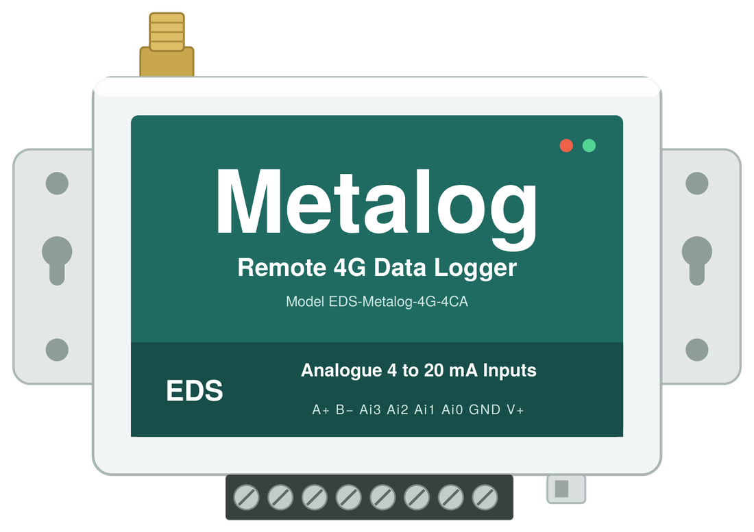
Metalog 4G is a compact remote data logger for water and wastewater networks. It reads up to four 4 to 20 mA transmitters and multiple RS485 Modbus RTU instruments, and returns the data over the 4G cellular network.
Level, pressure and flow transmitters all land on one 8 way terminal block. The 9 to 28 V DC supply range suits common 12 V and 24 V site supplies, and when the logger is fed from its DC jack, the V+ terminal powers loop powered transmitters at the same voltage.
Every setting is made on site from a laptop over USB, and two status lights show at a glance whether the logger is in setup, armed or sending.
One terminal block, every connection.
Power, analogue and RS485 wiring all land on a single 8 way terminal block, with the USB configuration port and power switch on the same face.
- RS485
- A+Pin 8: RS485 data A+
- B−Pin 7: RS485 data B−
- Analogue input
- Ai3Pin 6: Analogue input 4, 4 to 20 mA
- Ai2Pin 5: Analogue input 3, 4 to 20 mA
- Ai1Pin 4: Analogue input 2, 4 to 20 mA
- Ai0Pin 3: Analogue input 1, 4 to 20 mA
- 9 to 28 V DC
- GNDPin 2: Ground: supply negative, and the three wire 0 V common
- V+Pin 1: Power in, or sensor power out
- Power in or outWire 9 to 28 V DC to V+ and GND, pins 1 and 2. Or plug the supply into the DC jack, and V+ then powers your sensors at the supply voltage.
- Analogue inputsA two wire transmitter runs from V+ to its input, and all loops share V+. A three wire transmitter on its own supply shares 0 V with the logger GND.
- RS485A+ to A+ and B− to B− on every device, daisy chained along one bus, with a unique address for each Modbus device.
Switch the logger off before making or changing connections, and check each transmitter's polarity and supply voltage against its own datasheet.
Where it works.
Pump stations
Wet well level from a submersible level transducer.
Reservoirs
Storage level in tanks and reservoirs.
Network pressure
Pressure transmitters at critical points in the reticulation.
Flow metering
Analogue or Modbus outputs from flow meters.
Specifications
Metalog 4G in detail.
Sensor interface
| Analogue inputs | 4 channels, Ai0 to Ai3, 4 to 20 mA (default) |
|---|---|
| Transmitters | Two wire, loop powered from the logger V+, or three wire on an external supply |
| Ports | 1 × RS485, two wire (A+, B−) |
| Serial modes | Modbus RTU, or transparent RS485 transmission |
Telemetry
| Cellular | 4G |
|---|---|
| Antenna | SMA female connector, 50 Ω |
| SIM card | Hinged slot on the rear panel |
| Configuration | On site, from a laptop over USB |
Power
| Supply voltage | 9 to 28 V DC |
|---|---|
| Terminal input | V+ and GND, pins 1 and 2 |
| DC jack | 5.5 × 2.5 mm, 2.5 mm centre pin |
| Sensor power | V+ output at supply voltage when powered from the DC jack |
| Power switch | On / off |
Enclosure and environment
| Dimensions | 88 × 60 × 25 mm (W × H × D) |
|---|---|
| Protection | IP58 |
| Operating temperature | −20 to 80 °C |
| Mounting | Side flanges, 10 mm wide, with keyhole slots |
| Terminal block | 8 way, 3.81 mm pitch |
| Indicators | ACT (red) and SRV (green) LEDs |
Status lights
| Setup mode | ACT flashes every 600 ms |
|---|---|
| Disarmed | ACT flashes every 6 s |
| Armed | ACT flashes twice every 3 s |
| Starting or sending | SRV on |
| Start up or send complete | SRV off |
Ordering
| Model | EDS-Metalog-4G-4CA |
|---|---|
| Matched to your site | Transmitters, antennas and enclosures, by the EDS team |
Specifications are subject to change without notice. Full details are in the Metalog 4G datasheet.
Put your instruments on 4G.
Tell us the site, the instruments and the supply you have. Our team can match transmitters, antennas and enclosures to your site.